

Mitsubishi Elevator LEHY-II Weighing Device Adjustment Method
Composition of weighing device
1.1 of LEHY-II series elevator
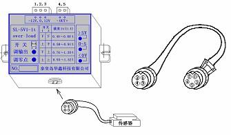
It consists of pressure sensor, matching device and its connecting wires: the pressure sensor is
installed under the rope head plate, and its matching device is installed in the control panel.
1.2 Circuit Connections.
The weighing device SL-5V1 has terminal blocks - 12V, 0V,+12V, OUT (+), OUT (-). Where OUT
The (-) pin and the 0V pin are connected internally. OUT (+) and OUT (-) are output voltage signals (DC, measurable). The wiring terminals+12V, - 12V, OUT (+), OUT (-) should be respectively connected to P01 (+12V), P02 (- 12V), P03 (WG), P04 (GND) on connector KG on P1 board.
1.3 Debugging
1.3.1 Indicator light shows that
a), When the output is less than 0, the yellow<0V indicator is on.
b), When the output is greater than 0 but less than 5V, the green 0-5 indicator light is on.
c), When the output is greater than 5V, the red indicator light>5V is on.
1.3.2 Debugging
General suggestions: In order to ensure that the output value is within the same range, it is better to adjust the output value to the range of 0.5V (no-load) to 4.5V (rated load).
Adjust the initial output value: when the elevator car is empty, adjust the potentiometer of "zero
adjustment" counterclockwise to turn on the yellow<0V indicator light, and then adjust the potentiometer of "zero adjustment" clockwise to turn off the yellow<0V indicator light, and then adjust it to the voltage measurement value of 0.5V at the output end to stop. At this time, the initial value adjustment is finished.
Adjust the output value:
Description.
a) SL-5V1 has two potentiometers: the "output adjustment" potentiometer and the "zero adjustment" potentiometer. The "zero adjustment" potentiometer is used to adjust the initial value; "Output regulation" potentiometer is used for output regulation. Both potentiometers are adjusted clockwise, and the output value increases; Turn counterclockwise to reduce the output value.
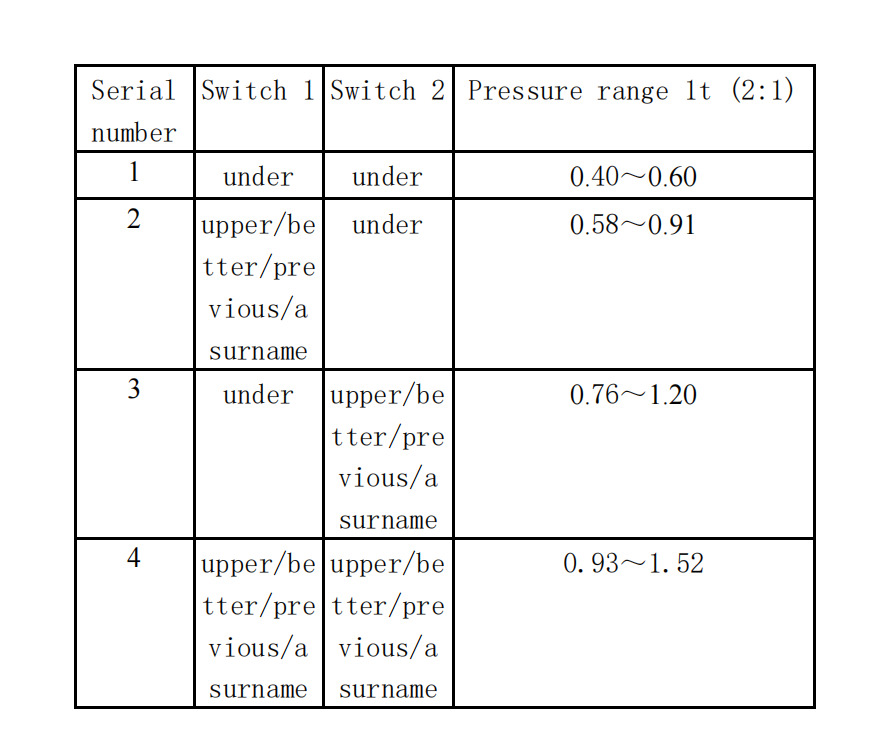
b) Two adjustment switches are set on the SL-5V1 at the same time to facilitate accurate adjustment in a large range. When both switches are pulled down, the instrument can be adjusted to 5V output under small load; When both switches are pulled, the instrument can be adjusted to 5V output under the maximum load. There are 4 combinations of 2 switches. 1) , install rated load on the lift car, select the first combination (switch 1 and switch 2 are both downward) to adjust the potentiometer (output adjustment) anticlockwise, turn the green indicator light on, and the measured voltage at the output terminal is 4.5V; If the green indicator light cannot be turned on (at this time, the red indicator light should always be on), select the second switch combination (switch 1 up, switch 2 down), and then adjust; If the requirements cannot be met again, select the third switch combination (switch 1 downward, switch 2 upward), and then adjust. If the requirements cannot be met again, select the fourth switch combination (switch 1 is upward, switch 2 is upward), turn the green indicator light on, and the measured voltage at the output terminal is 4.5V.
Note: To ensure accuracy, the switch combination setting should start from the first and change to the fourth combination in sequence, not the other way around.
After the setting of the load controller, the weighing data is written according to the randomized file.
1.3.4 Check the output value of the weighing device as follows:
(1) Turn the switch "MON" to "1", and turn the lift car to the position where the seven segment code display shows the value "0".
(2) Turn the switch "MON" to "C", and the seven segment code display should display values between "- 10" and "10".
1.3.5 If the display value is out of range, check as follows:
(1) Check whether the weighing device is normal (whether the pressure sensor is fully compacted).
(2) Check whether the wire tension is normal.
1.3.6 Setting of the final value of the weighing device
1.3.6.1 P203728B000 setting
(1) Write unloaded data to flash memory
If the car is empty, stop the car in the center of the shaft.
② Switch AUTO/HAND to HAND position and MNT/FWR switch to FWR position.
③ Turn the switch MON to 2, and the seven segment code display on P1 board will display the current weight value.
④ Turn the LD0/LD1 switch to the LD0 position for more than 1 second, and then release it. If the writing is successful, the display will flash for about 2 seconds and then stop flashing.
⑤ Turn the switch MON back to 6, and turn the MNT/FWR switch back to the middle position.
(2) Writing half-loaded data to flash memory
①Place a weight equal to 50% of the rated load inside the car and stop the car in the center of the shaft.
② Switch AUTO/HAND to HAND position and MNT/FWR switch to FWR position.
③ Turn the switch MON to 2, and the seven segment code display on P1 board will display the current weight value.
④ Turn the LD0/LD1 switch to the LD1 position for more than 1 second, and then release it. If the writing is successful, the display will flash for about 2 seconds and then stop flashing.
⑤ Turn the switch MON back to 6, and turn the MNT/FWR switch back to
the middle position. Note: The following methods can ensure that the
lift car stops in the middle of the hoistway:
Set the switch MON to 1, and move the lift car to the position where the seven segment display shows
"0" or "- 0". Since the displayed value changes 1 bit every 256mm, the distance from the lift car to
the midpoint will not exceed 256mm when "0" or "- 0" is displayed. (3) Write unbalanced load data to
flash memory
(1) The car stops on the ground floor unloaded.
② In the automatic operation mode, turn DCB/FMS to the FMS position, and then release it, and the floor display starts flashing.
③Closing the door, the elevator will automatically run from the bottom floor to the top floor, and when it reaches the top floor normally, the floor display stops blinking.
(4) Fine-tuning of overload action points, the
①The elevator is in fully automatic operation mode, and a weight equivalent to 110% of the rated load is placed inside the car.
② Adjust the switch WGHO until the overload detector 29W is activated, the car door remains open, and the overload buzzer sounds.
1.3.6.2 P203758B000 setting (C language)
(1) Write unloaded data to flash memory
①Confirm that the car is empty
② Manually drive the car to the midpoint of the shaft (refer to the method of confirming that the car
stops at the midpoint of the shaft).
③ Turn the rotary switch "SET1" on P1 board to "6" and "SET0" to "2".
④ Press the SW1 ↑/SW1 ↓ switch on the P1 board to the SW1 ↓ side, and the 7-segment code will display the current scale value, flash, and finish writing.